
티스토리 뷰
새로운 회로를 구상할 때 파워를 구성해야 하고 당근 해당 IC 정보를 검색하게 됩니다. DC-DC를 사용할까, LDO를 쓸까... DC-DC는 어떤걸 사용할까... 뭐 자주하는 고민인데요. 해당 IC 제조사 홈페이지에 들어가 보면 DC-DC도 종류가 많습니다. 크게는 step-up, step-down. 그 하위 카테고리에도 종류가 많습니다. 파워쪽은 잘 알지는 못해서 위키에 들어가 간단하게 정리차원에서 카피해 보았습니다.
1. Boost converter
step-up, SMPS (switched-mode power supply)
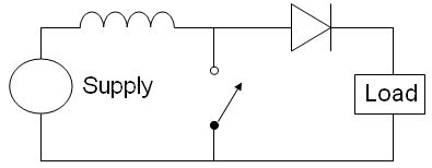
at least two semiconductors (a diode and a transistor) and at least one energy storage element: a capacitor, inductor, or the two in combination. To reduce voltage ripple, filters made of capacitors (sometimes in combination with inductors) are normally added to such a converter's output (load-side filter) and input (supply-side filter).
2. Buck converter
step-down, SMPS

containing at least two semiconductors (a diode and a transistor, although modern buck converters frequently replace the diode with a second transistor used for synchronous rectification) and at least one energy storage element, a capacitor, inductor, or the two in combination.
To reduce voltage ripple, filters made of capacitors (sometimes in combination with inductors) are normally added to such a converter's output (load-side filter) and input (supply-side filter).
Switching converters (such as buck converters) provide much greater power efficiency as DC-to-DC converters than linear regulators, which are simpler circuits that lower voltages by dissipating power as heat, but do not step up output current.
3. Charge pump
A charge pump is a kind of DC to DC converter that uses capacitors for energetic charge storage to raise or lower voltage. Charge-pump circuits are capable of high efficiencies, sometimes as high as 90–95%, while being electrically simple circuits.

Charge pumps use some form of switching device to control the connection of a supply voltage across a load through a capacitor. In a two stage cycle, in the first stage a capacitor is connected across the supply, charging it to that same voltage. In the second stage the circuit is reconfigured so that the capacitor is in series with the supply and the load. This doubles the voltage across the load - the sum of the original supply and the capacitor voltages. The pulsing nature of the higher voltage switched output is often smoothed by the use of an output capacitor.
An external or secondary circuit drives the switching, typically at tens of kilohertz up to several megahertz. The high frequency minimizes the amount of capacitance required, as less charge needs to be stored and dumped in a shorter cycle.
Charge pumps can double voltages, triple voltages, halve voltages, invert voltages, fractionally multiply or scale voltages (such as ×3/2, ×4/3, ×2/3, etc.) and generate arbitrary voltages by quickly alternating between modes, depending on the controller and circuit topology.
They are commonly used in low-power electronics (such as mobile phones) to raise and lower voltages for different parts of the circuitry - minimizing power consumption by controlling supply voltages carefully.
4. Buck-boost converter
The buck–boost converter is a type of DC-to-DC converter that has an output voltage magnitude that is either greater than or less than the input voltage magnitude. It is equivalent to a flyback converter using a single inductor instead of a transformer.
Two different topologies are called buck–boost converter. Both of them can produce a range of output voltages, ranging from much larger (in absolute magnitude) than the input voltage, down to almost zero.
The inverting topology
The output voltage is of the opposite polarity than the input. This is a switched-mode power supply with a similar circuit topology to the boost converter and the buck converter. The output voltage is adjustable based on the duty cycle of the switching transistor. One possible drawback of this converter is that the switch does not have a terminal at ground; this complicates the driving circuitry. However, this drawback is of no consequence if the power supply is isolated from the load circuit (if, for example, the supply is a battery) because the supply and diode polarity can simply be reversed. When they can be reversed, the switch can be on either the ground side or the supply side.

A buck (step-down) converter combined with a boost (step-up) converter
The output voltage is typically of the same polarity of the input, and can be lower or higher than the input. Such a non-inverting buck-boost converter may use a single inductor which is used for both the buck inductor mode and the boost inductor mode, using switches instead of diodes, sometimes called a "four-switch buck-boost converter", it may use multiple inductors but only a single switch as in the SEPIC and Ćuk topologies.
'Digital Developer' 카테고리의 다른 글
| MATLAB Training Course Brochure (0) | 2019.10.03 |
|---|---|
| 아두이노 나노 Arduino Nano 33 IOT (0) | 2019.09.28 |
| 아두이노 나노 Arduino Nano Every (0) | 2019.09.08 |
| B-L475E-IOT01A1 (0) | 2019.07.13 |
| macOS에서 깨져 보이는 자막 수정 (0) | 2017.05.01 |